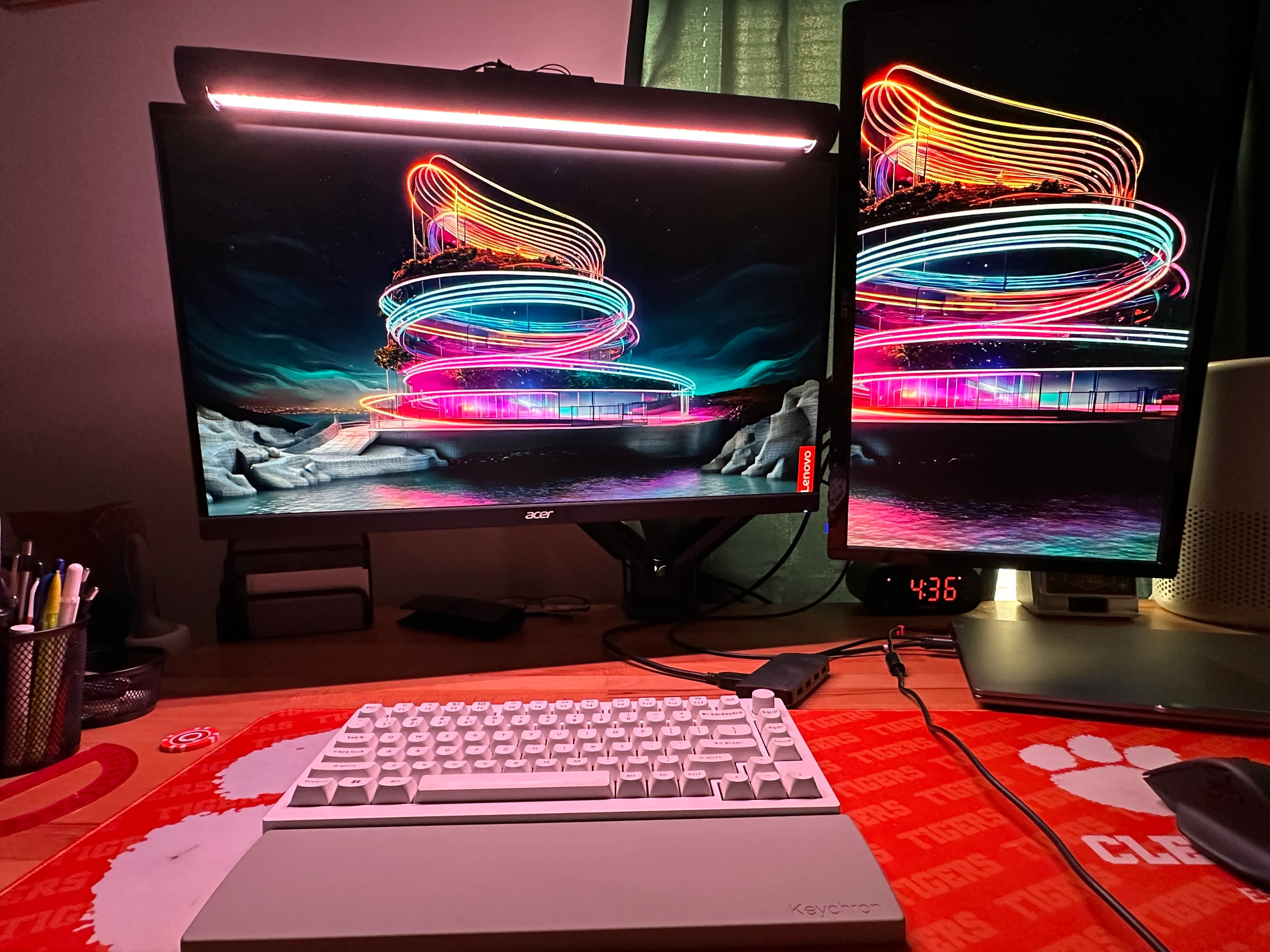
Monitor Light Bar
Inspiration
I wanted a monitor light bar that would be able to light up my desk and my keyboard without taking much space. However, quality light bars with the features I wanted were too expensive for me. So instead, I decided to create a dupe of the one I wanted, the BenQ ScreenBar Halo.
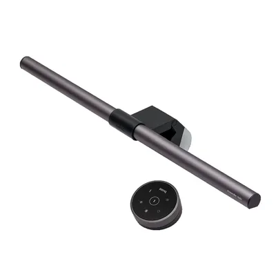
The Design
The main features I wanted in my light bar were:
- Light across my desk and keyboard
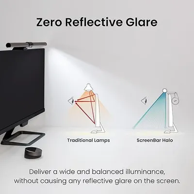
- The asymmetric light distribution for monitor glare
- The ability to control the light bar with my keyboard
- Biased lighting in the back of the light bar
- A stable clamp that would not fall off my monitor
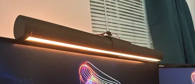
The final light bar is combination of a 3D printed enclosure, a WS2812B LED strip for the lighting, an ESP32 for the controller, a 5V 8A power supply, a mirror for assymetric light distribution, a polycarbonate sheet for diffusion, and air dry clay for a stable clamp weight.
Monitor Light Bar:
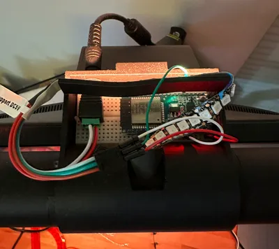
ESP32 Housing:
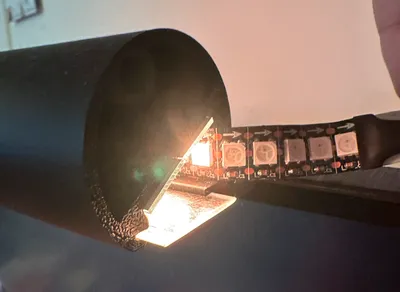
Assymetric Light Distribution Design:
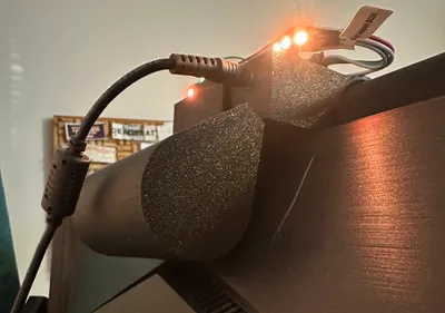
Back Clamp Weight:
Bill of Materials
3.2 ft WS2812B LED Strip (144 LEDs/m) - $12.99
5v 8A 40W Power Supply - $18.49
Power Jack Barrel Connector - $3.97
1/2” x 5” Mirrors - $13.88
ESP32 - $9.99
1/32” Thick Polycarbonate Sheet - $9.99
Air Dry Clay - $6.67
Wooden Dowels - $0.78
Rubber Feet - $6.99
Miscellaneous Wires, Screws - $5.00
3D Printing - Already have access to a 3D printer
Breadboard - Already had one
Super Glue - Already had some
Total Cost: $88.75
How it was Made
I’ve included the STL files if you want to build this yourself, but please note this is a personal
project and I didn’t take the time to make the design easily manufacturable as I also
used plenty of parts I already had laying around and don’t have links to.
CAD and Software are linked here: https://github.com/mystica-l/monitor-light-bar
3D Printed Enclosure
I started with designing the 3D printed enclosure. I wanted the bar to be long enough and to rotate so I separated the project into two parts, the main bar, and everything else. The main bar I decided was going to be 20 inches long because that fit my monitor and also meant that 4 mirrors side by side would be 20 inches long as well.
Because of the length and my 3D printer’s size restrictions, I had to print the main bar into three pieces.
Monitor Light Bar Center and Sides:
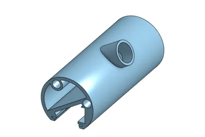
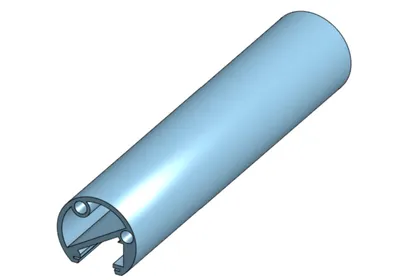
The center would be surrounded by 1 of each side totaling 20 inches. The center has a hole where the LEDs would route out of the bar to gain access to the ESP32 and power supply. Now for the inside of the main bar.
Monitor Light Bar Cross Section:
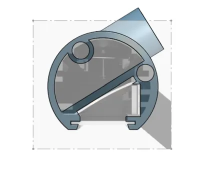
You can see an overlayed picture I found of the BenQ ScreenBar Halo’s cross section. I used this as a guide to get the same asymmetric light distribution. The main bar dimensions sported the following to adapt to the known size of parts I was using:
- The width of the the channel for the mirrors is 1 inch allowing you to stack 2 mirrors.
- The channel for the LED strip is the same width as the LED strip, 0.5 inches.
- The channel for the polycarbonate sheet is arbitrary length but slightly more than 1/32” thick.
- There are 0.27” holes for the 0.25” dowels to secure everything with super glue.
- Additionally, there’s a larger main channel to not take up space and allow the LED strip to route back around the end of the bar and back to the center to connect to the ESP32 and power supply.
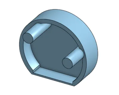
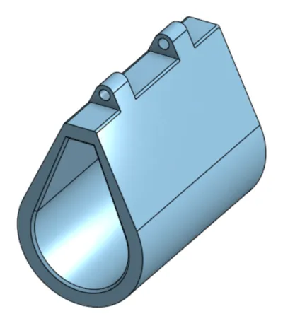
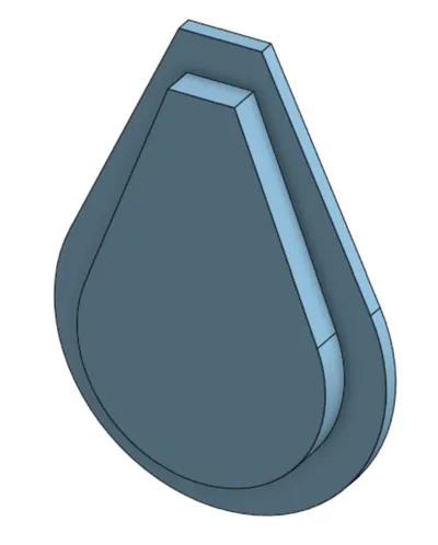
- I also designed “caps” to hide the ends of the bar and allow for a cleaner look. Monitor Light Bar Cap:
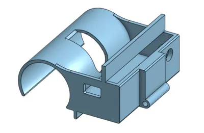
Once the main bar was designed and printed, I designed the combination clamp/ESP32 housing. I started with a snap on clamp that would hold the main bar to the monitor. The clamp was designed with the tolerance to flex to insert the main bar but ensure it didn’t fall. The main bar would then be able to rotate as needed. A hole was added so the extension of the mainbar that routed wires could pass through. The clamp also came with a lip to sit on the monitor.
The ESP32 housing was then designed to be essentially an extension of the clamp. This housing would hold the ESP32 sitting on a breadboard and have a hole for USB cable access, a pressfit hole for the power jack, and a structure for the bias lighting to sit on. In addition, there was a an area to join a back clamp weight to ensure the clamp would not fall off the monitor.
After that, I designed the final part that would clamp onto the back of the monitor. I wanted this to be heavy to ensure that the bar would not fall off the monitor. I decided to use air dry clay to fill the clamp and make it heavy and hollowed out the inside of the back clamp to accomplish this. I designed it to also pair with press fit caps to seal the clay.
Assembly
- Print all the parts
- Attach the 3 main bar pieces together with super glue and dowels
- Insert the mirrors into the main bar with super glue being careful to align them properly
- Peel the adhesive backing off the LED strip and insert it into the main bar. Only peel up to the point where the LED strip will be inserted. After that, route the LED strip back through the main bar and out the hole in the center of the main bar.
- Cut a piece of polycarbonate sheet to fit into the main bar and sand it. Sanding the polycarbonate sheet will help diffuse the light and make it more uniform. Insert the polycarbonate sheet into the main bar.
- Snapfit the main bar into the clamp and ensure it fits snugly and can rotate.
- Peel the adhesive backing off to stick it to the bias lighting structure.
- Attach an ESP32 to a breadboard and insert it into the housing.
- Wire the ESP32 to the LED strip and barrel jack. I used this guide: https://www.youtube.com/watch?v=exAWzMfmwQ8&t=368s Start at 5:30 and go until he shows you how to setup the barrel jack to power with the power supply.
- Pressfit the barrel jack into the housing.
- Fill the back clamp with air dry clay and pressfit the caps onto the back clamp.
- Attach the back clamp with an M4 screw and nut approximately 2.5 inches long.
- Super glue in the end caps to the main bar.
- Attach rubber feet to the bottom of the clamp for extra grip.
Software
Software wise, with the assistance of ChatGPT, I was able to write a simple program
to find my keyboard’s HID and use that to connect to the ESP32 over BLE. My keyboard has tri-mode
so I can switch back and forth between my laptop and my light bar.
Code and installation instructions are linked on the repo: https://github.com/mystica-l/monitor-light-bar
The software allows for adjustment of brightnes, color, and an on/off switch
using the volume knob and arrow keys on my keyboard.